Well, we have a new web address, but the old one works too. The new address is http://www.moldengineeringsoftware.com/
The original address, http://www.dzynsource.com/, also works just fine. It will, hopefully, make it easier for people doing a search to find us.
Monday, September 27, 2010
Monday, May 31, 2010
How Much Plastic Do You Need?
Calculate Amount of Plastic To Be Processed Per Hour
Calculating the amount of material per hour that you will be processing is a fairly simple calculation, but with DZynSource for Molds it's even easier.
From the main menu, choose the "Production Calculations" command button.

Figure 1. DZynSource Main Screen
This is one of the few calculations that can be chosen from more than one sub-menu. It can also be found under the "Molding Calculations" sub-menu.

The blank form for doing this particular production calculation is fairly self explanatory. You first choose the unit of weight for the plastic molded part. In my experience, the part weight is usually measured in grams. The industry that I work in, caps and closures, packaging, medical disposables, and so forth, the parts are fairly small and usually measured in grams. The ounces and pounds are there for the molders, mold makers and other personnel that work with the larger parts.
 So, choose the unit of measurement for the part weight, enter the number of cavities in the mold, and enter the cycle time in seconds. If the mold is full hot runner, then there will be no cold runner to allow for and you enter zero for the runner weight.
If the mold has any amount of cold runner, enter it in the text box next to "Enter runner weight in grams".
The unit of weight for the runner changes with the units chosen for the molded part, so that they are always in the same units.
Press calculate, and that's all there is to it. You can press clear to clear all fields and start again, press "Print" to send a copy of the form to the default printer, or press "Menu" to return to the Main Screen. The solved example below is for a 12-gram part being produced by a 64-cavity full hot runner mold that runs a 10 second cycle. As you can see, you'll be processing almost 610 pounds of material per hour. The equivalent weight in kilograms is also given.

Calculating the amount of material per hour that you will be processing is a fairly simple calculation, but with DZynSource for Molds it's even easier.
From the main menu, choose the "Production Calculations" command button.
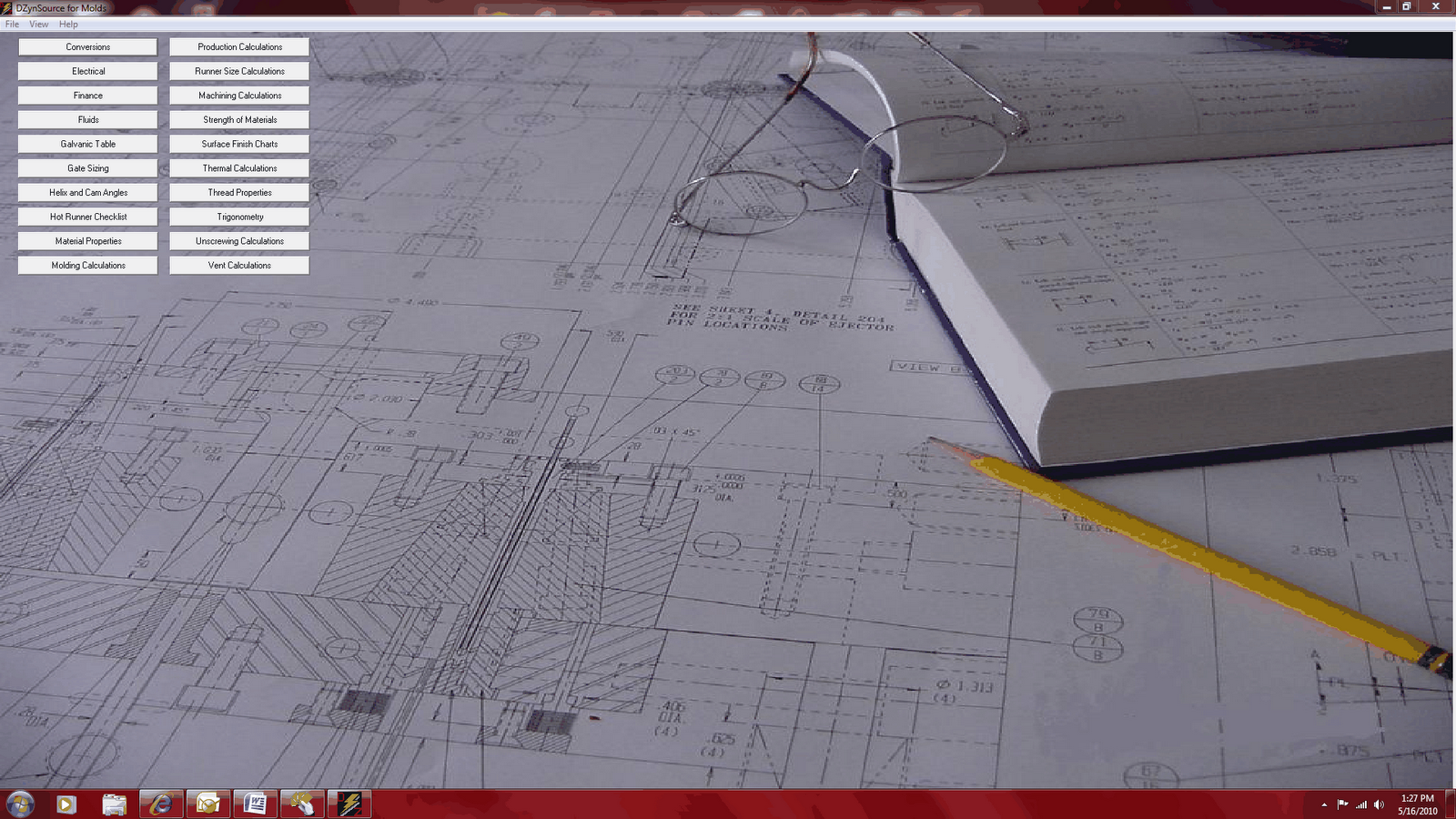
Figure 1. DZynSource Main Screen
This is one of the few calculations that can be chosen from more than one sub-menu. It can also be found under the "Molding Calculations" sub-menu.


The blank form for doing this particular production calculation is fairly self explanatory. You first choose the unit of weight for the plastic molded part. In my experience, the part weight is usually measured in grams. The industry that I work in, caps and closures, packaging, medical disposables, and so forth, the parts are fairly small and usually measured in grams. The ounces and pounds are there for the molders, mold makers and other personnel that work with the larger parts.
If the mold has any amount of cold runner, enter it in the text box next to "Enter runner weight in grams".
The unit of weight for the runner changes with the units chosen for the molded part, so that they are always in the same units.
Press calculate, and that's all there is to it. You can press clear to clear all fields and start again, press "Print" to send a copy of the form to the default printer, or press "Menu" to return to the Main Screen. The solved example below is for a 12-gram part being produced by a 64-cavity full hot runner mold that runs a 10 second cycle. As you can see, you'll be processing almost 610 pounds of material per hour. The equivalent weight in kilograms is also given.

Wednesday, May 26, 2010
Pneumatic Cylinders Made Simple
Pneumatic cylinder calculations can be done in a matter of minutes, if not seconds, with DZynSource. From the main screen choose the "Fluids" command button. The Fluids sub-menu appears, and you'll want to select the "Pneumatic Cylinder Calculations" command.

 The blank pneumatic cylinder form appears. As with almost all of the calculations within DZynSource, you must choose metric or imperial units to work with as your first step.
The calculation provides a size, and you would choose the next larger size of standard cylinder. For example, if you needed to push with a force of 450 pounds, and you have a line pressure of 80 p.s.i., you would need a 3.758 inch diameter piston. You would choose the next larger standard size, or 4 inch diameter piston. See the picture below.
In this case we have calculated an appropriate piston size, which is 4.000 diameter. I next entered all of my know data for the project that I'm working on. The piston I chose has a 1.000 diameter rod, a 12 inch stroke, a compressed air supply at 80 pounds per square inch, and we need to cycle the cylinder 10 times per minute, or every 6 seconds. Press calculate and we see that the forward force will be just over 1000 pounds. The return force is always less that the forward force because we have to subtract the piston diameter from the piston diameter. The air cannot act on the area of the piston rod. We are also given the standard cubic feet per minute of air that will be required to run this cylinder at this cycle. This information is used to determine the extra compressor load, and to size the valves that will control the air flow. That's all there is to it.

 The blank pneumatic cylinder form appears. As with almost all of the calculations within DZynSource, you must choose metric or imperial units to work with as your first step.
You are now offered the option of calculating what size pneumatic cylinder you need to accomplish your task. If you know the force that must be generated, you enter that into the text box provided next to the "Enter the force that the cylinder must generate" text. You are also asked enter the air pressure that will be provided to the cylinder. The sizing of the piston is based on this premise: you want to deliver a force that is double the minimum force required. A smaller cylinder will move slower, due to being under-powered. a larger cylinder will usually move slower too, due to the increased volume of air required.
The calculation provides a size, and you would choose the next larger size of standard cylinder. For example, if you needed to push with a force of 450 pounds, and you have a line pressure of 80 p.s.i., you would need a 3.758 inch diameter piston. You would choose the next larger standard size, or 4 inch diameter piston. See the picture below.

In this case we have calculated an appropriate piston size, which is 4.000 diameter. I next entered all of my know data for the project that I'm working on. The piston I chose has a 1.000 diameter rod, a 12 inch stroke, a compressed air supply at 80 pounds per square inch, and we need to cycle the cylinder 10 times per minute, or every 6 seconds. Press calculate and we see that the forward force will be just over 1000 pounds. The return force is always less that the forward force because we have to subtract the piston diameter from the piston diameter. The air cannot act on the area of the piston rod. We are also given the standard cubic feet per minute of air that will be required to run this cylinder at this cycle. This information is used to determine the extra compressor load, and to size the valves that will control the air flow. That's all there is to it.
Sunday, May 16, 2010
Hydraulic Cylinder Calculations The Easy Way
Hydraulic cylinder calculations need to be done quite often, as a matter of course, when designing molds. These calculations are done effortlessly, and in a matter of seconds, with DZynSource for Molds Software. The following steps show the beauty and simplicity of our software for doing this and other common mold engineering tasks:
1. This is the main screenshot from DZynSource for Molds, in this case click on the "Fluids" command button.

The Fluids sub-menu appears, and you choose the "Hydraulic Cylinder Calculations" command button.


The blank Hydraulic Cylinder worksheet appears, ready for you to enter your known data. The second article that I wrote on this blog used the following example:
You have a hydraulic cylinder with a 2.000 diameter piston, a 1.000 diameter rod, a 12-inch stroke, and want to extend the rod in .5 seconds, and the system pressure is 1000 pounds per square inch. Calculate the forward and return forces generated and the flow rate, in gallons per minute, of hydraulic oil required to accomplish the stroke outwatd in .5 seconds.
We'll enter this data into the Hydraulics worksheet:
First, choose the units that you want to work in, enter the data, Press Enter, and Voila, all of your answers appear.

Customers will very often call to find out how many gallons per minute their hydraulic pump will need to delivery to the mold, particularly with unscrewing molds. You can answer them in the blink of an eye, and not have to take the time to figure it out and call them back. What if scenarios are worked out fast as you can think of them. DZynSource for Molds really does save time, and enables you to create better designs.
As always, over designing is expensive, under-designing can be disastrous!
Tuesday, November 24, 2009
How to Calculate the SCFM Required To Actuate a Pneumatic Cylinder

When designing with pneumatic cylinders, it is often desirable to calculate the standard cubic feet per minute (SCFM) of air required to operate the cylinder. This article will explain how to do that calculation.
Let's assume, for example, that you are using a double acting (reciprocating) air cylinder with a 2-inch bore and a 12-inch stroke. Let's further assume that it reciprocates at 10 cycles per minute using 90-P.S.I.G. of air. If you want to know what the required scfm flow-rate of the air to the cylinder is, use the following equation:
Q2 = P2 x Q1 / P1
Where;
Q2 equals the quantity of compressed air required to operate the cylinder based on the volume of the cylinder bore for a given stroke, forward and return.
P1 equals the atmospheric pressure, which is 14.7 pounds per square inch.
P2 equals the gauge pressure of the compressed air being used to activate the cylinder.
Q1 = the piston area * (2 * stroke) * the number of cycles per minute / 1728.
Q2 equals the volume of uncompressed air required.
The area for a 2-inch bore = Pi/4 * D^2 = 3.14-in^2
12-inch stroke, Pressure, P2 = 90-Psig
Cycles = 10 cycles /min
Dividing by 1728 converts cubic inches to cubic feet.
Q1 = Piston area * (2 * stroke) * cycles/minute / 1728
Q1 = 3.14-in2 x (2 x 12) x 10 / 1728 = 753.98 / 1728 = .4363-ft3/ min (cubic feet per minute)
Q2 = P2 x Q1 / P1 = 104.7 x .4363 / 14.7 = 3.11 scfm (standard cubic feet per minute)
So, your compressor and valve must be able to supply 3.11 standard cubic feet per minute of air to operate your cylinder for this design.
When doing these calculations, disregard the piston rod cross-sectional area, and assume that the temperature remains constant. The value "P2" equals the gauge pressure plus the atmospheric pressure, which is 14.7 p.s.i.
The photo is courtesy of Parker Automation Products
Sunday, November 22, 2009
How to Calculate The Pressure Drop Through An Orifice
Sometimes we engineers and designers spend too much time and money designing around large water fittings because we think that mold performance will be significantly hampered by the use of small fittings. It’s not necessarily true, and I want to show you why, and what IS important.
Darcy’s equation is used to calculate pressure losses in fluid system pipes and drilled passages.
Darcy's equation is: (f * (L/D) * ((v^2) / 2g))
To calculate pressure loss, two additional factors are introduced as follows:
Pressure Losses = (f * (L/D) * ((v^2) / 2g)) * (.433 * Sg )
where,
f = a friction factor,
L = the length of the pipe or passage,
D = the diameter of the pipe, or passage, in inches,
v = the fluid velocity in feet per second
g = gravitational acceleration constant (32.2 ft per second / per second)
Sg = the specific gravity of the fluid, water is approximately 1, for other fluids consult your literature or fluid supplier.
The .433 * Sg factor converts what would be called "head loss", in units of feet, into pounds per square inch. Since L/D is a ratio, the units are unimportant as long as the same units are used for both length and diameter.
The factor “f” (friction factor) can be found on charts available from hose and fitting suppliers, and in most Fluid Dynamics texts. These charts usually require you to be able to define the surface roughness in the passage. The one that is probably the most familiar to engineers is Moody's diagram.
There are two equations that I use to calculate the friction factor, that have been found to be appropriate for molds. The first, used for calculations involving turbulent flow, is called Blasius’ Law, and is as follows:
f = .3164 / ((Reynolds Number)^.25)
The second, used for Laminar flow, is:
f = 64 / (Reynolds Number)
One more calculation is required. Darcy’s equation requires the fluid velocity, in feet per second, as input. Since we rarely know this, we must convert the quantity that we usually know, which is usually the flow rate in gallons per minute, into feet per second.
The conversion from gallons per minute to feet per second is as follows:
v = (GPM * 231 in^2 / 60 seconds per minute / Area in inches^2 / 12)
To calculate the area of our hole diameter (Area in inches input), we use the familiar A = ((D ^ 2) * Pi) / 4
GPM is gallons per minute; and there are 231 cubic inches in a gallon. We divide by 60 to convert from minutes to seconds; the A is area of the hole diameter, and the division by 12 converts inches to feet.
Finally, we have the tools required to be able to calculate the pressure drop through our fittings. We’ll do two sample calculations, one each for a .375 and .718” diameter holes, to compare the difference.
For the .375 diameter hole, and using 6 gallons per minute of 60-degree water, we’ll calculate the Reynolds Number:
Re = (3160*Q) / [(Diameter in inches)) * (viscosity in centistokes)]
Re = (3160*6) / (.375 * 1.12) = 37920 / .42 = 45,142
Pressure Losses = (f * (L/D) * ((v^2) / 2g)) * (.433 * Sg )
f = .3164 / ((Reynolds Number)^.25) = .0217
A= .375^2 * Pi/4 = .11045
v = (6 * 236 / 60 / .11045 / 12 ) = 17.43
Press. Loss = .0217 * (.375 / 1) * [(17.43^2) / (2 * 32.2)] * (.433 *1) = .139 p.s.i.
For the .718 diameter hole, and using 6 gallons per minute of 60-degree water, we’ll calculate the Reynolds Number:
Re = (3160*Q) / [(Diameter in inches)) * (viscosity in centistokes)]
Re = (3160*6) / (.718 * 1.12) = 37920 / .80 = 23,577
Pressure Losses = (f * (L/D) * ((v^2) / 2g)) * (.433 * Sg )
f = .3164 / ((Reynolds Number)^.25) = .0255
A= .718^2 * Pi/4 = .40489
v = (6 * 236 / 60 / .40489 / 12) = 4.75
Press. Loss = .0255 * (.718 / 1) * [(4.75^2) / (2 * 32.2)] * (.433 *1) = .0054 p.s.i.
Now, on a percentage basis, there is a huge difference, but on an absolute basis, you are not likely to notice any difference in mold performance by changing between these two fittings, in this situation.
A quick look at the equation shows us that the only non-linear relationship is the velocity, which gets squared. Therefore, proportional increases in velocity will have a greater effect on pressure drop that any other factor. This is why it is so important to actually engineer your mold design.
Let’s see what would happen if you used a fitting with a .125 diameter hole.
For the .125 diameter hole, and using 6 gallons per minute of 60-degree water, we’ll do the calculations:
Re = (3160*Q) / [(Diameter in inches)) * (viscosity in centistokes)]
Re = (3160*6) / (.125 * 1.12) = 18960 / .14 = 135,428
Pressure Losses = (f * (L/D) * ((v^2) / 2g)) * (.433 * Sg )
f = .3164 / ((Reynolds Number)^.25) = .0165
A= .125^2 * Pi/4 = .01227
v = (6 * 236 / 60 / .01227 / 12) = 156.86
Press. Loss = .0165 * (.125 / 1) * [(156.86^2) / (2 * 32.2)] * (.433 *1) = 21.829 p.s.i.
Keep in mind that 6 gallons per minute will provide a Reynolds Number of 8200 in six .344 diameter water lines, assuming 60-degree water with no glycol added, so it’s not likely that you would ever end up in a situation where you would try to push 6 gallons per minute through a .125 diameter hole.
The water fittings used on a mold are most often dictated by shop standards. If the molding department only has hoses with “353” series fittings, then that is what you will usually have to design around. If you are designing for a molder that has standardized on “251” series fittings, this may or may not be causing you problems. The point of the article is this: it is not always immediately obvious how much affect your choice of pipe tap and water-fitting sizes are having on mold performance. If calculations can be done in minutes, or seconds, does it make any sense to skip over this critical step? You can make better decisions if you have more information. As always, over design can be expensive, and under design can be disastrous.
This is a segment of an article that I originally wrote for Moldmaking Technology Magazine. The link to the original article is here:
http://www.moldmakingtechnology.com/articles/090604.html
One very real problem with small fittings is that they are often used with small inside diameter hoses. Do these calculations for 20 feet of hose with small inside diameter. You may find that your largest pressure drops are outside the mold. If you need to use small fittings, be sure to reduce down at the end of the hose, and use as large a hose diameter as possible.
It can be a little time consuming to run through all of these calculations manually, so it is best to either create a spreadsheet, or purchase a program, that will allow you to do “what if” scenarios quickly. Once this is programmed, the calculations can be done in a matter of seconds, or minutes.
Sunday, November 15, 2009
How to Do Basic Hydraulic Cylinder Calculations

Designing with hydraulic cylinders is very common in everything from injection molds to log splitters to Backhoes and more. Here are some of the most basic calculations used in these applications.
This article shows you how to do the three most basic, and common, calculations for designing with hydraulic cylinders. These three would be the forward force of the cylinder, the return force, and flow rate required for the forward portion of the cycle. The return flow rate and force are lower because the volume and area are reduced by the presence of the piston rod, and therefore is not included in these calculations. The working portion of the hydraulic cylinder cycle should be the piston forward movement, for the above-mentioned reasons.
The first choice to be made is the units you wish to work with, inch or metric.
To calculate the forces generated by the piston, you must enter the appropriate diameter or diameters and the pressure supplied to the cylinder, in the appropriate units. In order to calculate the required volumetric flow rate, you must also use the length of stroke and the time is seconds.
The familiar relationships for area are used to calculate these answers:
Piston forward area = (Piston diameter)^2 x Pi / 4
Piston return area = ((Piston diameter)^2 - (Rod diameter)^2) x Pi / 4
Force = Pressure x Area
GPM = (((Pi * (D^2)) / 4) * S) * (60 / 231) / T
where,
GPM = gallons per minute
D = Piston diameter in inches
S = Stroke in inches
T = time in seconds
the 60 factor converts seconds to minutes
If you have a hydraulic cylinder with a 2.000 diameter piston, a 1.000 diameter rod, a 12-inch stroke, and want to extend the rod in .5 seconds, and the system pressure is 1000 p.s.i., the calculations for force and gallons per minute are as follows.
Piston forward area = 2^2 x Pi/4 = 4 x Pi / 4 = Pi = 3.142 inches^2 (rounded)
Piston return area = ((2)^2 - (1)^2) x Pi / 4 = 2.356 inches^2
Forward Force = 1000 x 3.142 = 3142 pounds
Return Force = 1000 x 2.356 = 2356 pounds
Since the time to extend the piston rod is only affected by the diameter of the piston, we can ignore the piston's rod size.
GPM = (((Pi * (D^2)) / 4) * S) * (60 / 231) / T
GPM = ((3.142 x 4)/4) * S) x (60/231) / .5 = 19.58 gallons per minute.
Of course, if you are going to a have a continuously cycling hydraulic cylinder, you must do the flow rate calculations for both the piston side, and the rod side.
Do not exceed the manufacturers recommendation for pressure in your hydraulic cylinder. Make sure that there are pressure and temperature relief valves for safety, and if in doubt, get professional advice.
Picture courtesy Parker Hannafin.
Subscribe to:
Posts (Atom)