
Metric screw sizes are calculated as follows:
Minor diameter = Major diameter - (1.226869 x pitch)
Pitch diameter = Major diameter - (.649519 x pitch)
The tensile stress area = ((root dia + pitch dia) / 2)^2 * Pi/4
Inch screw sizes are calculated as follows:
Minor diameter = Major diameter - (1.299038 x pitch)
Pitch diameter = Major diameter - (.649519 x pitch)
The tensile stress area = ((minor dia + pitch dia) / 2)^2 * Pi/4
Thursday, April 28, 2011


Calculate Optimum Diameter For Cutter Or Part
When machining, it is occasionally desirable to calculate the appropriate diameter of either the cutter (i.e. milling) or the workpiece (i.e. turning) when the Surface Feet per Minute are known, and the RPM's are established.
The equation used in this calculation is: Diameter = (SFM / RPM) / (Pi * 12)
where, SFM = Surface Feet per Minute,
RPM = Revolutions per Minute, and
Pi = 3.141592654
When using DZynSource Mold Engineering Software to do the calculation, go to "Machining Calculations" / "Surface Feet Per Minute" and then choose "Diameter" from the option boxes.
 Enter the RPM's and he surface feed per minute in the appropriate text boxes. Press Calculate. The answer appears in the Answer frame.
Use the Clear button to clear all fields, however this is not necessary in order to do another calculation. You may simply type over the previous entries.
You may send the page to your default printer by pressing Print.
Press Menu to return to the main menu selection area.
The equation used in this calculation is: Diameter = (SFM / RPM) / (Pi * 12)
where, SFM = Surface Feet per Minute,
RPM = Revolutions per Minute, and
Pi = 3.141592654
When using DZynSource Mold Engineering Software to do the calculation, go to "Machining Calculations" / "Surface Feet Per Minute" and then choose "Diameter" from the option boxes.

Use the Clear button to clear all fields, however this is not necessary in order to do another calculation. You may simply type over the previous entries.
You may send the page to your default printer by pressing Print.
Press Menu to return to the main menu selection area.
Wednesday, April 27, 2011
DZynSource Mold Engineering Software Feature List
Unit Conversions Section - Over 300 separate conversions
Converter for Hours into Days or WeeksD.C. Electrical Calculations: 9 Different Ohm's Law Calculations
Fluids Calculations:
Bubbler sizing Continuity Eq. | ||||
Equivalent Hydraulic Diameter - General Case | ||||
Equivalent Hydraulic Diameter - Annular Channel | ||||
Hydraulic Cylinder Calculations | ||||
Pneumatic Cylinder Calculations | ||||
Pressure Losses (Darcy's Equation) | ||||
Pressure Loss or Flow Rate Through an Orifice | ||||
Pressure Losses in Valves and Fittings | ||||
Reynolds Number Calculations | ||||
Gate Sizing: Hot Tip, Edge Gate, & Sub-Gate
Helix and Cam Angles
Hot Runner Checklist - set up as a word processor so you can add your own items.
Machining Calculations:
effective Cutter Diameter
Feed Rate / Feed Per Tooth
Inches per minute <> Inches Per Revolution
Surface Feet Per Minute
Surface Roughness
3-Sided Cutter Angle Calculator
Material Properties:
36 different molds making steels, aluminums, and high conductivity alloys.
Can open up to 4 properties lists for easy comparison.Mold and Plate Weight Calculator: steel or aluminum, based on solid block size
Molding Calculations:
Chiller Sizing, includes the number of BTU's of heat to be removed per hour, the gallons per minute of water required to remove the heat content of the plastic.
Clamp force table, by material type
Cooling Time Estimator - Ballman Shusman method
Colorant Let Down Weight Calculator
Minimum Mold Open Time- time for the highest part to drop below the mold
Pounds or Kilograms of Material per hour
Plastic Shrink Rate Table and Steel and Plastics Size Calculator
Tie Bar Stretch
Production Calculations:
Pounds or Kilograms of Material per hour (Second location, for convenience)
Molding Capacity: single or multi-molds. Parts per minute, hour, day, week,4 weeks, and year.
Converter for Hours into Days or Weeks (Second location, for convenience)
Number of cavities required, based on production needs.
Number of plastic parts that can be molded in a given time.
Time to mold a certain quantity of parts.
Runner Size Calculator
Strength of Materials Calculations:
Beam Deflections, 9 different loading and support scenarios
Circular discs, fixed or supported circumference, uniform load or spot load
Round Cavity Expansion, due to internal pressure. Through bore or blind pocket.
Elastic Strain:
Uniform Cross-section, single material
Uniform Cross-section, two materials assembly
Tapered Cross-section, single material
Hoop Stress
Leader Pin Bend Calculator, with 1, 2, or 3 moving plates; with plate weight estimator Long Column with central loading, critical load calculator
L/K Test to determine if the long column calculator is the appropriate method.
Moment of Inertia Calculator, also calculates area, Radius of Gyration, Section Modulus, and distance to extreme fiber of 10 common geometric shapes.
Mold Plate Expansion due to internal pressure. Designed especially for side action molds. Includes blind or through pocket comparison.
Surface Finish Tables: SPI/SPE comparison, RA vs. RMS inch and metric, grinding grit & VDI
Thermal Calculations:
Thermal Expansion Coefficient calculator for 30 different mold making metals. Calculate expansion, initial size, or final size.
Chiller Sizing, includes the number of BTU's of heat to be removed per hour, the gallons per minute of water required to remove the heat content of the plastic. (Second location, for convenience)
Thread Properties:
Three wire size, also includes largest, smallest and best wire size. Inch and metric.
Pipe Threads: Tap drills size for N.P.T. and B.S.P.T. threads, with & w/out pipe reamer.
Properties of Threads: includes major, minor, and tap drill diameters. Also includes tensile stress area and a torque calculator.
Trigonometry
Circular segment calculator
Decimal degrees to Degrees, Minute, Seconds Converter. Works for both directions.
Right Angle Trigonometry.
Roll Dimension Calculator, Obtuse and acute angles.
Sine plate gage block calculator.
Tooling ball dimension calculator.Unscrewing Mold Calculations
Vent Calculator
Vent depth table, by material type.
Vent width calculator.
Friday, April 1, 2011
New Release of DZynSource Mold Engineering Software
April 1, 2011
A new version of DZynSource Mold Engineering Software is live on our web site. Now with more features than ever. You can now calculate how much a mold cavity will expand, with either a through-hole, or a blind cavity pocket.
Circular disc bending and deflection can now be calculated. This is great for check the strength of a round core with a top center gate. There are a total 4 options in this section: perimeter fixed or supported with uniform load, or smaller concentric load on either support type.
There's a new capacity and utilization feature that covers single or multiple mold packages, and automatically calculates how many parts per day, week, 4 weeks, and per year all based on your input.
There are many more additions to the software, and I'll be posting on them in the near future.
www.dzynsource.com or www.moldengineeringsoftware.com
A new version of DZynSource Mold Engineering Software is live on our web site. Now with more features than ever. You can now calculate how much a mold cavity will expand, with either a through-hole, or a blind cavity pocket.
Circular disc bending and deflection can now be calculated. This is great for check the strength of a round core with a top center gate. There are a total 4 options in this section: perimeter fixed or supported with uniform load, or smaller concentric load on either support type.
There's a new capacity and utilization feature that covers single or multiple mold packages, and automatically calculates how many parts per day, week, 4 weeks, and per year all based on your input.
There are many more additions to the software, and I'll be posting on them in the near future.
www.dzynsource.com or www.moldengineeringsoftware.com
Sunday, February 20, 2011
Sønderborg Værktøjsfabrik A/S Purchases DZynSource Software
Wednesday, December 29, 2010
Another DZynSource Mold Engineering Software Commendation!
We have another new commendation:
“Every mold making company should own a copy. Great idea, great implementation.”
Jim Philippe / Tooling Engineer CORNING LIFE SCIENCES
Thank you, Jim.
“Every mold making company should own a copy. Great idea, great implementation.”
Jim Philippe / Tooling Engineer CORNING LIFE SCIENCES
Thank you, Jim.
Thursday, December 23, 2010
New DZynSource Commendation!
We just received a new, and very nice, commendation about our software:
“ I am impressed with your software; talk about practical and useful! Anyone in the business can sure appreciate what you have done.”
Brett Niggel, Designer, Studio One Eleven
Thank you for the kind words, Brett!
“ I am impressed with your software; talk about practical and useful! Anyone in the business can sure appreciate what you have done.”
Brett Niggel, Designer, Studio One Eleven
Thank you for the kind words, Brett!
Monday, December 6, 2010
A Partial List of DZynSource Features
Unit Conversion Section
D.C. Electrical Calculations
Fluids: Bubbler sizing , Equivalent Hydraulic Diameter - General Case, Equivalent Hydraulic Diameter - Annular Channel, Hydraulic Cylinder Calculations, Pneumatic Cylinder Calculations, Pressure Losses (Darcy's Equation), Pressure Loss or Flow Rate Through an Orifice, Pressure Losses in Valves and Fittings,
Reynolds Number Calculations
Galvanic Table
Gate Sizing, Hot Tip , Edge Gate, Sub-Gate
Helix and Cam Angle Calculations
Hot Runner Checklist
Properties of Metals Tensile strength, yield strength, elongation, impact strength, reduction of area, all at various hardnesses.
Molding Calculations: Chiller Sizing, Clamp Force Requirements, Cooling Time Estimator - Ballman and Shushman Method, Minimum Mold open Time - Time for highest part to clear bottom of mold, Mold Fill Time Calculator, Pounds or Kilograms of Plastic per Hour - Also in production calculations, Tie Bar Stretch .
Production Calculations: Quantity of Cavities Required, Quantity of Parts that be can molded, Time to Mold a Quantity of Parts, Pounds or Kilograms of Plastic per Hour - Also in molding calculations.
Runner Size Calculations
Machining Calculations: Effective Cutting Diameter, Feed Rate / Feed Per Tooth, IPM <> IPR, Surface Feet Per Minute, Surface Roughness, Three-Sided Cutter Calculator.
Strength of Materials: Beam Deflections - 9 different loading and support scenarios, Elastic Strain - How Much a Part Stretches or Compresses under Load, Hoop Stress - Stress and Strain in Circular Rings, Long Column Sudden Failure Calculations & the L/K Long Column Test, Moment of Inertia, Section Modulus, Area, Radius of Gyration, and Distance from Neutral Axis To Extreme Fiber in 10 Standard Geometric Shapes, Mold Plate Pocket distortion, Through Pocket and Blind Pocket.
Surface Finish Comparison Tables
Thermal Calculations: Expansion, Initial Size, Final Size, Coefficients of thermal expansion for 30 common mold making materials.
Thread Properties: Properties of Metric and Inch Threads, Course and Fine, Major Diameter, Tensile stress area in inches and millimeters, Minor diameter area, tap drill size, and torque calculator
Three Wire Measurement, Largest Wire - Threads per Inch or Pitch Know, Smallest Wire - Threads per Inch or Pitch Known, Best Wire - Threads per Inch or Pitch Known, Measurement over Wire - Threads per Inch or Pitch Known,
Pipe Threads: Tap drill sizes for N.P.T. and B.S.P.T threads, with and without pipe reamer,
Trigonometry: Chord, DD <> DMS, Right Angle Trigonometry, Roll Dimensions, Acute and Obtuse angles, Sine Plate Dimensions, degrees, minutes, seconds, or decimal degrees, any sine plate length, Tooling Ball Dimensions.
Unscrewing Mold Calculations - in threads per inch or by pitch, Stroke per revolution, Number of turns required, Minimum stroke, Cam Rise, Total Rise for stroke.
Vent Calculations: Table of typical vent depths, by material and a Vent Width Calculator.
Extensive Help files with a great deal of data and reference information.
D.C. Electrical Calculations
Fluids: Bubbler sizing , Equivalent Hydraulic Diameter - General Case, Equivalent Hydraulic Diameter - Annular Channel, Hydraulic Cylinder Calculations, Pneumatic Cylinder Calculations, Pressure Losses (Darcy's Equation), Pressure Loss or Flow Rate Through an Orifice, Pressure Losses in Valves and Fittings,
Reynolds Number Calculations
Galvanic Table
Gate Sizing, Hot Tip , Edge Gate, Sub-Gate
Helix and Cam Angle Calculations
Hot Runner Checklist
Properties of Metals Tensile strength, yield strength, elongation, impact strength, reduction of area, all at various hardnesses.
Molding Calculations: Chiller Sizing, Clamp Force Requirements, Cooling Time Estimator - Ballman and Shushman Method, Minimum Mold open Time - Time for highest part to clear bottom of mold, Mold Fill Time Calculator, Pounds or Kilograms of Plastic per Hour - Also in production calculations, Tie Bar Stretch .
Production Calculations: Quantity of Cavities Required, Quantity of Parts that be can molded, Time to Mold a Quantity of Parts, Pounds or Kilograms of Plastic per Hour - Also in molding calculations.
Runner Size Calculations
Machining Calculations: Effective Cutting Diameter, Feed Rate / Feed Per Tooth, IPM <> IPR, Surface Feet Per Minute, Surface Roughness, Three-Sided Cutter Calculator.
Strength of Materials: Beam Deflections - 9 different loading and support scenarios, Elastic Strain - How Much a Part Stretches or Compresses under Load, Hoop Stress - Stress and Strain in Circular Rings, Long Column Sudden Failure Calculations & the L/K Long Column Test, Moment of Inertia, Section Modulus, Area, Radius of Gyration, and Distance from Neutral Axis To Extreme Fiber in 10 Standard Geometric Shapes, Mold Plate Pocket distortion, Through Pocket and Blind Pocket.
Surface Finish Comparison Tables
Thermal Calculations: Expansion, Initial Size, Final Size, Coefficients of thermal expansion for 30 common mold making materials.
Thread Properties: Properties of Metric and Inch Threads, Course and Fine, Major Diameter, Tensile stress area in inches and millimeters, Minor diameter area, tap drill size, and torque calculator
Three Wire Measurement, Largest Wire - Threads per Inch or Pitch Know, Smallest Wire - Threads per Inch or Pitch Known, Best Wire - Threads per Inch or Pitch Known, Measurement over Wire - Threads per Inch or Pitch Known,
Pipe Threads: Tap drill sizes for N.P.T. and B.S.P.T threads, with and without pipe reamer,
Trigonometry: Chord, DD <> DMS, Right Angle Trigonometry, Roll Dimensions, Acute and Obtuse angles, Sine Plate Dimensions, degrees, minutes, seconds, or decimal degrees, any sine plate length, Tooling Ball Dimensions.
Unscrewing Mold Calculations - in threads per inch or by pitch, Stroke per revolution, Number of turns required, Minimum stroke, Cam Rise, Total Rise for stroke.
Vent Calculations: Table of typical vent depths, by material and a Vent Width Calculator.
Extensive Help files with a great deal of data and reference information.
Plastics Today Article about DZynSource
The article that I mentioned in a previous post has been released today, December 6, 2010. Their web site appears to be down for maintenance at the moment, but I am sure it will be up soon.
http://www.facebook.com/l.php?u=http%3A%2F%2Fwww.plasticstoday.com%2Fimm%2Farticles%2Ftessy-plastics-dzynsource-mold-engineering-software&h=5efda
http://www.facebook.com/l.php?u=http%3A%2F%2Fwww.plasticstoday.com%2Fimm%2Farticles%2Ftessy-plastics-dzynsource-mold-engineering-software&h=5efda
Saturday, November 20, 2010
ProWrite Communications Doing Article about DZynSource Mold Engineering Software
I got some really nice news today. Clare Goldsberry, Owner at ProWrite Communications, Sr. Editor at Modern Plastics Worldwide, and Senior Editor at Canon Communications, is going to write an article about DZynSource Mold Engineering Software. I am honored and quite excited!
Clare saw a press release that I issued this week about Tessy Plastics buying my software. She remembered my name from when we were both writing for Injection Molding Magazine. She was a senior editor, at the time, and I was writing book reviews for the IMM Book Club. Thank you Clare.
I'll post a link to the article, when it goes live.
Clare saw a press release that I issued this week about Tessy Plastics buying my software. She remembered my name from when we were both writing for Injection Molding Magazine. She was a senior editor, at the time, and I was writing book reviews for the IMM Book Club. Thank you Clare.
I'll post a link to the article, when it goes live.
Friday, October 29, 2010
Side Action Flash, Part 1, Mold Engineering Software
Have you ever seen a mold with the side action flashing across the split face? Have you checked the design and the steel over and over only to find that the dimensions appear to be correct? The flash problem may be due to an under-designed mold plate. This is particularly true with “A”-side action molds for large parts, and even more so when the side action is contained in a mold plate with a “through-pocket”, like the one shown below.

In this case, each part has 1.25 square inches of surface area for the cavity pressure to generate force on. This force must be overcome by the strength of the plate. Let’s assume that the cavity pressure is 10,000 p.s.i., which is not an unreasonable assumption. This is a 4-cavity mold, so the force trying to separate the slide faces is 50,000 pounds.

You can see from the calculation here that the center of the plate, left as designed, would blow apart approximately .0012 inches, which would probably flash when molding a polypropylene part. In this case, as you can see in the drawing, the plate weakness was overcome by installing an interlock between the slide pocket plate and the stripper plate. This interlock gave the plate enough additional strength to mold flash-free parts. Of course, if the designer had the DZynSource Mold Engineering Software, this problem could have been avoided by doing “what if” scenarios with plate sizes and thicknesses to come to a more robust design that would not flash without extra mold components.

In this case, each part has 1.25 square inches of surface area for the cavity pressure to generate force on. This force must be overcome by the strength of the plate. Let’s assume that the cavity pressure is 10,000 p.s.i., which is not an unreasonable assumption. This is a 4-cavity mold, so the force trying to separate the slide faces is 50,000 pounds.

You have two types of plate distortion to calculate here: one is the stretching of the 2 legs that form the upper and lower boundaries (the ends) of the pocket. You can get a better visualization of that in the DZynSource Mold Engineering Software screenshot shown below. The other distortion is the “bow” of the sides of the pocket, again see the DZynSource screenshot.
You can see from the calculation here that the center of the plate, left as designed, would blow apart approximately .0012 inches, which would probably flash when molding a polypropylene part. In this case, as you can see in the drawing, the plate weakness was overcome by installing an interlock between the slide pocket plate and the stripper plate. This interlock gave the plate enough additional strength to mold flash-free parts. Of course, if the designer had the DZynSource Mold Engineering Software, this problem could have been avoided by doing “what if” scenarios with plate sizes and thicknesses to come to a more robust design that would not flash without extra mold components.
Monday, October 18, 2010
How Much Will That Round Tapered Part Stretch or Crush?
When an object of round tapered cross section is subjected to tension or compression within the elastic limit of the material, the deformation can be approximated with the equation:
¶ = FL/(p E R1 R2)
Where
¶ = = the deformation
F = the load or force
L = the length of the object in the direction that the force is acting
p = Pi (3.14159265358979)
E = the Modulus of Elasticity of the material
R1 = the radius at the small end of the cone
R2 = the radius at the large end of the cone
This equation works for tapered cylinders that don't get too small at the small end. The answers become meaningless (they approach infinity) as the radius approaches zero.
You have to use several menus to get to this form. From the Main menu, choose “Strength of Materials”; from there choose “Elastic Strain”. Once the Elastic Strain sub-menu is open, you have three choices; choose “Tapered Cross-Section, Single Material”.

When entering the required information, it is imperative that the units used are consistent. For instance, if pounds per square inch are used for the modulus of elasticity, quantities must be entered in units of pounds and inches.
First choose whether you want to use p.s.i. or N/mm²; next choose how many places beyond the decimal point you like the answer carried.
Enter the Force, the length, the large radius, the small radius, and the Modulus of Elasticity in the text boxes next to the questions asked. When entering modulus of elasticity values like 30,000,000 pounds per square inch, as would usually be used for steel, you may enter as 30e6 as a shortcut.
Press Calculate. The strain and stress values are shown on a separate Answers form. Answers are valid if the stress is from a static load and is within the elastic limit of the material in question.
Use the Clear button to clear all of the text boxes; however this is not necessary in order to do another calculation. You may simply type over the previous entries.
You may send the page to your default printer by pressing Print.
Press Menu to return to the main menu selection area.
¶ = FL/(p E R1 R2)
Where
¶ = = the deformation
F = the load or force
L = the length of the object in the direction that the force is acting
p = Pi (3.14159265358979)
E = the Modulus of Elasticity of the material
R1 = the radius at the small end of the cone
R2 = the radius at the large end of the cone
This equation works for tapered cylinders that don't get too small at the small end. The answers become meaningless (they approach infinity) as the radius approaches zero.
You have to use several menus to get to this form. From the Main menu, choose “Strength of Materials”; from there choose “Elastic Strain”. Once the Elastic Strain sub-menu is open, you have three choices; choose “Tapered Cross-Section, Single Material”.

When entering the required information, it is imperative that the units used are consistent. For instance, if pounds per square inch are used for the modulus of elasticity, quantities must be entered in units of pounds and inches.
First choose whether you want to use p.s.i. or N/mm²; next choose how many places beyond the decimal point you like the answer carried.
Enter the Force, the length, the large radius, the small radius, and the Modulus of Elasticity in the text boxes next to the questions asked. When entering modulus of elasticity values like 30,000,000 pounds per square inch, as would usually be used for steel, you may enter as 30e6 as a shortcut.
Press Calculate. The strain and stress values are shown on a separate Answers form. Answers are valid if the stress is from a static load and is within the elastic limit of the material in question.
Use the Clear button to clear all of the text boxes; however this is not necessary in order to do another calculation. You may simply type over the previous entries.
You may send the page to your default printer by pressing Print.
Press Menu to return to the main menu selection area.
How Many Surface Feet per Minute is That?
It is sometimes desirable to calculate the quantity of surface feet per minute attained, when the diameter of the rotating cutter (i.e. milling) or the work piece (i.e. turning) is known, and the RPM's are established. The equation used in this calculation is:
SFM = (Pi * Diameter * RPM) / 12
where, SFM = Surface Feet per Minute, RPM = revolutions per minute
 You can find the Surface Feet Per Minute calculator under the "Machining Calculations" sub-menu.

Enter the diameter and revolutions per minute in the appropriate text boxes. Press Calculate. The answer appears in the Answer frame.
Use the Clear button to clear all fields, however this is not necessary in order to do another calculation. You may simply type over the previous entries.
You may send the page to your default printer by pressing Print.
Press Menu to return to the main menu selection area.
SFM = (Pi * Diameter * RPM) / 12
where, SFM = Surface Feet per Minute, RPM = revolutions per minute

Enter the diameter and revolutions per minute in the appropriate text boxes. Press Calculate. The answer appears in the Answer frame.
Use the Clear button to clear all fields, however this is not necessary in order to do another calculation. You may simply type over the previous entries.
You may send the page to your default printer by pressing Print.
Press Menu to return to the main menu selection area.
Thursday, October 7, 2010
Compression in a Multi-Material Component With Uniform Cross Section
When an object is constructed with two different materials, and both have uniform cross-section, and both are subjected to the same tension or compression within the elastic limit of the material, the forces, stresses, and deformation can be predicted with the following equations:
F1 = F * (A1 * E1) / ((A1 * E1) + (A2 * E2))
F2 = F * (A2 * E2) / ((A1 * E1) + (A2 * E2))
¶ = (F1 * L) / (A1 * E1) = (F2 * L) / (A2 / E2)
Stress1 = F1 / A1
Stress2 = F2 / A2
Where
¶ = = the deformation
F = the total load or force acting on the objects
F1 = the load or force carried by object 1
F2 = the load or force carried by object 2
L = the length of the objects in the direction that the force is acting
E1 = the Modulus of Elasticity of the material for object 1
E2 = the Modulus of Elasticity of the material for object 2
A1 = The cross-sectional area of object 1, perpendicular to the force
A2 = The cross-sectional area of object 2, perpendicular to the force
It is assumed that the object is constructed in such a way that there is no slippage between objects 1 & 2.
When entering the required information into the DZynSource Mold Engineering Software, it is imperative that the units used are consistent. For instance, if pounds per square inch are used for the modulus of elasticity, quantities must be entered in units of pounds and inches. See the previous article to see you access this calculation from within DZinSource.

First choose whether you want to use p.s.i. or N/mm², then choose how many places beyond the decimal point you like the answer carried.
Enter the Force, the length, the outer objects area, the inner objects area, and the Modulus of Elasticity for each object in the text boxes next to the questions asked. When entering modulus of elasticity values, 30,000,000, as would usually be used for steel, may be entered as 30e6 as a shortcut. The area of 10 basic shapes can be calculated by choosing Strength of Materials, Moment of Inertia from the main menu, choosing the desired shape, and entering the required information.
Press Calculate. A separate answer page appears with the values for Force 1, Force 2, the deflection, and stress induced in each component are shown. Answers are valid if the stress from a static load is within the elastic limit of the material in question.

Use the Clear button to clear all entry fields, however this is not necessary in order to do another calculation. You may simply type over the previous entries.
Press OK on the answer page to close that page.
You may send the either page to your default printer by pressing Print.
Press Menu to return to the main menu selection area.
F1 = F * (A1 * E1) / ((A1 * E1) + (A2 * E2))
F2 = F * (A2 * E2) / ((A1 * E1) + (A2 * E2))
¶ = (F1 * L) / (A1 * E1) = (F2 * L) / (A2 / E2)
Stress1 = F1 / A1
Stress2 = F2 / A2
Where
¶ = = the deformation
F = the total load or force acting on the objects
F1 = the load or force carried by object 1
F2 = the load or force carried by object 2
L = the length of the objects in the direction that the force is acting
E1 = the Modulus of Elasticity of the material for object 1
E2 = the Modulus of Elasticity of the material for object 2
A1 = The cross-sectional area of object 1, perpendicular to the force
A2 = The cross-sectional area of object 2, perpendicular to the force
It is assumed that the object is constructed in such a way that there is no slippage between objects 1 & 2.
When entering the required information into the DZynSource Mold Engineering Software, it is imperative that the units used are consistent. For instance, if pounds per square inch are used for the modulus of elasticity, quantities must be entered in units of pounds and inches. See the previous article to see you access this calculation from within DZinSource.

First choose whether you want to use p.s.i. or N/mm², then choose how many places beyond the decimal point you like the answer carried.
Enter the Force, the length, the outer objects area, the inner objects area, and the Modulus of Elasticity for each object in the text boxes next to the questions asked. When entering modulus of elasticity values, 30,000,000, as would usually be used for steel, may be entered as 30e6 as a shortcut. The area of 10 basic shapes can be calculated by choosing Strength of Materials, Moment of Inertia from the main menu, choosing the desired shape, and entering the required information.
Press Calculate. A separate answer page appears with the values for Force 1, Force 2, the deflection, and stress induced in each component are shown. Answers are valid if the stress from a static load is within the elastic limit of the material in question.

Use the Clear button to clear all entry fields, however this is not necessary in order to do another calculation. You may simply type over the previous entries.
Press OK on the answer page to close that page.
You may send the either page to your default printer by pressing Print.
Press Menu to return to the main menu selection area.
Sunday, October 3, 2010
What The Heck Is Modulus of Elasticity?
The Machinery's Handbook defines Modulus of Elasticity as follows: "Modulus of Elasticity, E, (also called Young's modulus) is the ratio of unit stress to unit strain within the proportional limit of a material in tension or compression". In general, the Modulus of Elasticity, for steel is 30,000,000 p.s.i. Some steels are as low as 28,000,000 and some as high as 34,000,000 p.s.i.
Stress equals the force or load applied divided by the area that the force is applied to, or Stress=F/A.
Strain is the deformation, elongation or compression, that the material undergoes as a result of the force being applied to it.
The shear Modulus of Elasticity, G, also known as the Modulus of Rigidity, is also the ratio of stress to strain within the proportional limit of a material, but in shear. It is usually expressed as a percentage of the Modulus of Elasticity, E, in tension. The Modulus of Elasticity in shear, G, is usually about 38% of the Modulus of Elasticity in tension, E.
Some values for Modulus of Elasticity for some common materials are as follows:
Aluminum, Alcoa QC-7 10,300,000 p.s.i., or 71,000 MPa
Brush-Wellman's Moldmax XL Beryllium Copper 17,000,000 p.s.i. or 117,000 MPa
Brush-Wellman's Protherm Beryllium Copper 20,000,000 p.s.i. or 138,000 MPa
Ampco MoldMATE 90 22,000,000 p.s.i. or 152,000 MPa
Steel 30,000,000 p.s.i. or 207,000 MPa
Stress equals the force or load applied divided by the area that the force is applied to, or Stress=F/A.
Strain is the deformation, elongation or compression, that the material undergoes as a result of the force being applied to it.
The shear Modulus of Elasticity, G, also known as the Modulus of Rigidity, is also the ratio of stress to strain within the proportional limit of a material, but in shear. It is usually expressed as a percentage of the Modulus of Elasticity, E, in tension. The Modulus of Elasticity in shear, G, is usually about 38% of the Modulus of Elasticity in tension, E.
Some values for Modulus of Elasticity for some common materials are as follows:
Aluminum, Alcoa QC-7 10,300,000 p.s.i., or 71,000 MPa
Brush-Wellman's Moldmax XL Beryllium Copper 17,000,000 p.s.i. or 117,000 MPa
Brush-Wellman's Protherm Beryllium Copper 20,000,000 p.s.i. or 138,000 MPa
Ampco MoldMATE 90 22,000,000 p.s.i. or 152,000 MPa
Steel 30,000,000 p.s.i. or 207,000 MPa
How To Calculate The Effective Diameter for a Toroid Type Cutter
When cutting less than full depth with a toroid shaped cutter, the effective cutting diameter is smaller than the actual diameter of the cutter, and dependent on the depth of cut and the corner radius. This effective cutting diameter is used for feed and speed calculations. A toroid shaped cutter is a flat bottom cutter with corner a radius that is less than half of the cutter diameter.
The formula used to calculate the effective cutting diameter is as follows:
Effective cutter diameter = 2 * (((R ^ 2) - ((R - Depth) ^ 2)) ^ 0.5) + (D - 2 * R)
where;
Depth = the depth of cut
D = the cutter diameter
R = the corner radii
In the DZynSource Mold Engineering Software, you enter the cutter diameter, the corner radii, and the depth of cut in the appropriate text boxes, Press Calculate, and the answer appears above the Calculate button.

Use the Clear button to clear all fields, however this is not necessary in order to do another calculation. You may simply type over the previous entries.
You may send the page to your default printer by pressing Print.
Press Menu to return to the main menu of DZynSource Mold Engineering Software.
The formula used to calculate the effective cutting diameter is as follows:
Effective cutter diameter = 2 * (((R ^ 2) - ((R - Depth) ^ 2)) ^ 0.5) + (D - 2 * R)
where;
Depth = the depth of cut
D = the cutter diameter
R = the corner radii
In the DZynSource Mold Engineering Software, you enter the cutter diameter, the corner radii, and the depth of cut in the appropriate text boxes, Press Calculate, and the answer appears above the Calculate button.

Use the Clear button to clear all fields, however this is not necessary in order to do another calculation. You may simply type over the previous entries.
You may send the page to your default printer by pressing Print.
Press Menu to return to the main menu of DZynSource Mold Engineering Software.
How To Calculate The Effective Diameter for a Ball Nose Cutter
When cutting less than full depth with a ball nose cutter, the effective cutting diameter is smaller than the actual diameter of the cutter, and dependent on the depth of cut. This effective cutting diameter is used for feed and speed calculations.
The formula used to calculate the effective cutting diameter is as follows:
Effective Diameter = 2 * (((R ^ 2) - (R - Depth of cut) ^ 2) ^ 0.5)
where,
R = The Cutter Diameter divided by 2
In DzynSource Mold Engineering Software, simply Enter the cutter diameter and the depth of cut in the appropriate text boxes. Press Calculate. The answer appears above the Calculate button.

Use the Clear button to clear all fields, however this is not necessary in order to do another calculation. You may simply type over the previous entries.
You may send the page to your default printer by pressing Print.
Press Menu to return to the main menu selection area.
The formula used to calculate the effective cutting diameter is as follows:
Effective Diameter = 2 * (((R ^ 2) - (R - Depth of cut) ^ 2) ^ 0.5)
where,
R = The Cutter Diameter divided by 2
In DzynSource Mold Engineering Software, simply Enter the cutter diameter and the depth of cut in the appropriate text boxes. Press Calculate. The answer appears above the Calculate button.

Use the Clear button to clear all fields, however this is not necessary in order to do another calculation. You may simply type over the previous entries.
You may send the page to your default printer by pressing Print.
Press Menu to return to the main menu selection area.
Thursday, September 30, 2010
Calculate Chiller Tonnage, And Other Interesting Molding Facts
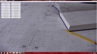
You can calculate your required chiller tonnage, gallons per minute of water cooling, and amount of material to be processed per hour in one quick step with DZynSource Mold Engineering Software.
From the main menu, choose the "Thermal Considerations" command button. This is one of the few calculations that can be chosen from more than one sub-menu within DZynSource. It can also be found under the "Molding Calculations" sub-menu.

The blank form for doing this particular production calculation is fairly self explanatory. You first choose the unit of weight for the plastic molded part. In my experience, the part weight is usually measured in grams. The industry that I work in, caps and closures, packaging, medical disposables, and so forth, the parts are fairly small and usually measured in grams. The ounces and pounds are there for the molders, moldmakers and other personnel that work with the larger parts. So, choose the unit of measurement for the part weight, enter the number of cavities in the mold, and enter the cycle time in seconds. If the mold is full hot runner, then there will be no cold runner to allow for and you enter zero for the runner weight. If the mold has any amount of cold runner, enter it in the text box next to "Enter runner weight in grams". The unit of weight for the runner changes with the units chosen for the part weight so that they are always in the same units.
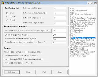
You'll need to enter the specific heat for the plastic being processed, and the units need to be in BTU"s per pound per degree Fahrenheit. If you click on the command button a list will appear with some generic materials to choose from. In this case I'm choosing an 8 gram part made from polypropylene homopolymer running in 32-cavity hot runner mold. Hence no runner weight. I've entered 450 degrees as the mold temperature and 170 degrees as the expected ejected part temperature. In general, a 5 degree rise in water temperature, between the in and out of any water line, is considered acceptable for general molding. 3 degrees is often used for technical molding. I entered 4 degrees here to sort of split the difference
Now that we've entered all of our information, it's time to press calculate. You can see that the answer box tells us that we'll be processing over 290 pounds of material per hour, and that that material will contain over 54,000 BTU's per hour of heat that must be removed. To do that, we need to force a total of 27 gallons per minute of water through the mold. The chiller capacity required to accomplish this transfer of heat is 4.52 tons.
You can press clear to clear all fields and start again, press "Print" to send a copy of the form to the default printer, or press "Menu" to return to the Main Screen. Calculations are quick and easy with DZynSource Mold Engineering Software. If you have any questions you can send them to sales at dzynsource.com. Visit us on the web at http://www.dzynsource.com or www.moldengineeringsoftware.com
You can calculate your required chiller tonnage, gallons per minute of water cooling, and amount of material to be processed per hour in one quick step with DZynSource Mold Engineering Software.
From the main menu, choose the "Thermal Considerations" command button. This is one of the few calculations that can be chosen from more than one sub-menu within DZynSource. It can also be found under the "Molding Calculations" sub-menu.

The blank form for doing this particular production calculation is fairly self explanatory. You first choose the unit of weight for the plastic molded part. In my experience, the part weight is usually measured in grams. The industry that I work in, caps and closures, packaging, medical disposables, and so forth, the parts are fairly small and usually measured in grams. The ounces and pounds are there for the molders, moldmakers and other personnel that work with the larger parts. So, choose the unit of measurement for the part weight, enter the number of cavities in the mold, and enter the cycle time in seconds. If the mold is full hot runner, then there will be no cold runner to allow for and you enter zero for the runner weight. If the mold has any amount of cold runner, enter it in the text box next to "Enter runner weight in grams". The unit of weight for the runner changes with the units chosen for the part weight so that they are always in the same units.

You'll need to enter the specific heat for the plastic being processed, and the units need to be in BTU"s per pound per degree Fahrenheit. If you click on the command button a list will appear with some generic materials to choose from. In this case I'm choosing an 8 gram part made from polypropylene homopolymer running in 32-cavity hot runner mold. Hence no runner weight. I've entered 450 degrees as the mold temperature and 170 degrees as the expected ejected part temperature. In general, a 5 degree rise in water temperature, between the in and out of any water line, is considered acceptable for general molding. 3 degrees is often used for technical molding. I entered 4 degrees here to sort of split the difference
Now that we've entered all of our information, it's time to press calculate. You can see that the answer box tells us that we'll be processing over 290 pounds of material per hour, and that that material will contain over 54,000 BTU's per hour of heat that must be removed. To do that, we need to force a total of 27 gallons per minute of water through the mold. The chiller capacity required to accomplish this transfer of heat is 4.52 tons.
You can press clear to clear all fields and start again, press "Print" to send a copy of the form to the default printer, or press "Menu" to return to the Main Screen. Calculations are quick and easy with DZynSource Mold Engineering Software. If you have any questions you can send them to sales at dzynsource.com. Visit us on the web at http://www.dzynsource.com or www.moldengineeringsoftware.com

Monday, September 27, 2010
DZynSource Mold Engineering Software
Well, we have a new web address, but the old one works too. The new address is http://www.moldengineeringsoftware.com/
The original address, http://www.dzynsource.com/, also works just fine. It will, hopefully, make it easier for people doing a search to find us.
The original address, http://www.dzynsource.com/, also works just fine. It will, hopefully, make it easier for people doing a search to find us.
Monday, May 31, 2010
How Much Plastic Do You Need?
Calculate Amount of Plastic To Be Processed Per Hour
Calculating the amount of material per hour that you will be processing is a fairly simple calculation, but with DZynSource for Molds it's even easier.
From the main menu, choose the "Production Calculations" command button.
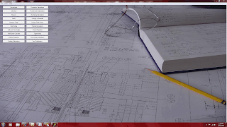
Figure 1. DZynSource Main Screen
This is one of the few calculations that can be chosen from more than one sub-menu. It can also be found under the "Molding Calculations" sub-menu.

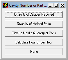
The blank form for doing this particular production calculation is fairly self explanatory. You first choose the unit of weight for the plastic molded part. In my experience, the part weight is usually measured in grams. The industry that I work in, caps and closures, packaging, medical disposables, and so forth, the parts are fairly small and usually measured in grams. The ounces and pounds are there for the molders, mold makers and other personnel that work with the larger parts.
 So, choose the unit of measurement for the part weight, enter the number of cavities in the mold, and enter the cycle time in seconds. If the mold is full hot runner, then there will be no cold runner to allow for and you enter zero for the runner weight.
If the mold has any amount of cold runner, enter it in the text box next to "Enter runner weight in grams".
The unit of weight for the runner changes with the units chosen for the molded part, so that they are always in the same units.
Press calculate, and that's all there is to it. You can press clear to clear all fields and start again, press "Print" to send a copy of the form to the default printer, or press "Menu" to return to the Main Screen. The solved example below is for a 12-gram part being produced by a 64-cavity full hot runner mold that runs a 10 second cycle. As you can see, you'll be processing almost 610 pounds of material per hour. The equivalent weight in kilograms is also given.

Calculating the amount of material per hour that you will be processing is a fairly simple calculation, but with DZynSource for Molds it's even easier.
From the main menu, choose the "Production Calculations" command button.
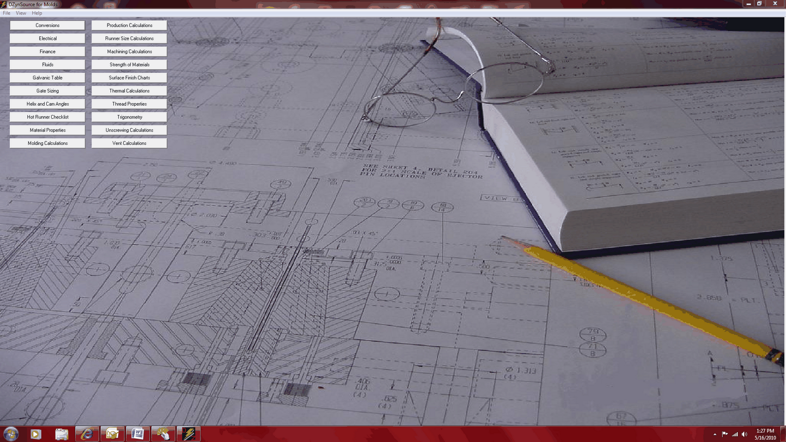
Figure 1. DZynSource Main Screen
This is one of the few calculations that can be chosen from more than one sub-menu. It can also be found under the "Molding Calculations" sub-menu.


The blank form for doing this particular production calculation is fairly self explanatory. You first choose the unit of weight for the plastic molded part. In my experience, the part weight is usually measured in grams. The industry that I work in, caps and closures, packaging, medical disposables, and so forth, the parts are fairly small and usually measured in grams. The ounces and pounds are there for the molders, mold makers and other personnel that work with the larger parts.

If the mold has any amount of cold runner, enter it in the text box next to "Enter runner weight in grams".
The unit of weight for the runner changes with the units chosen for the molded part, so that they are always in the same units.
Press calculate, and that's all there is to it. You can press clear to clear all fields and start again, press "Print" to send a copy of the form to the default printer, or press "Menu" to return to the Main Screen. The solved example below is for a 12-gram part being produced by a 64-cavity full hot runner mold that runs a 10 second cycle. As you can see, you'll be processing almost 610 pounds of material per hour. The equivalent weight in kilograms is also given.

Subscribe to:
Posts (Atom)